By TJ Cornish, September 2014
It doesn’t take long before a 20A 120V circuit starts to seem small. In this article series, we will take a look at several next steps.
A Word About Safety
Electricity can be dangerous. In addition to shock potential, electricity can also be a fire or arc flash hazard, particularly as voltage or available current increases. This article discusses commonly accepted electrical practices, but is far from exhaustive in its scope or treatment. When approaching an unknown electrical service large or small, do not assume that it is correctly wired or in working order. You must test it. A procedure for testing standard 120V 20A receptacles can be found here: Receptacle Testing
Any distribution equipment must be constructed to the standards of the regulating authorities in your area (The NEC and/or listing agency such as the UL in the case of the US); and some localities require that all equipment be UL or ETL listed for use; precluding homemade equipment.
This article is based on the US power system design and regulations. Much of this should be applicable to Canada and Mexico and other countries with similar designs; however the author is not familiar enough with those systems to speak with authority.
Definitions
Outlet – a receptacle providing electrical power. Most people mean a standard 120V 15A or 20A receptacle such as found in your home.
Circuit – the circuit breaker and all of the wiring downstream of the circuit breaker. The number of available circuits and the voltage and current ratings determine how much power is available. This is not to be confused with an outlet or receptacle, as frequently multiple receptacles are supplied by one circuit.
NEMA – a standard system of plugs and receptacles. NEMA ratings have three components: a plug series, a current rating, and an indication whether it is a plug or a receptacle. For example, a NEMA 5-20R indicates that this is a series 5 (120V) device, that it is rated at 20 amps, and that is a receptacle.
Edison plug/receptacle – a NEMA 5-15 plug or receptacle
Range plug/receptacle – a NEMA 14-50 plug or receptacle, providing a 50A 240V/208V circuit that can be used via a small distribution panel to provide up to 6 20A 120V circuits.
California plug/receptacle – a series of locking receptacles providing up to 50A in various configurations. The applicable model for our purposes is the CS6365C/CS6364C mating pair.
Distro – short for power distribution unit. A device that accepts a high-current supply, and breaks this power out into multiple lower-ampacity circuits.
Poor Man’s Distro – a device that provides a common ground for multiple Edison circuits, which provides many of the noise and safety benefits of a full distro, but doesn’t require a high-current supply.
Cam-Lok – a high-current single conductor connector used in a set to deliver power to a distro.
Multiple Circuits
We have reached the point where one circuit is not enough; the next step is finding additional circuits to use.
If you’re lucky, there may be several obvious circuits set up for use near the stage. If not, you may need to do a little investigating. There aren’t any hard and fast rules about the wiring scheme of a building, but you can make some educated guesses.
- If the venue was not originally designed for live events, the receptacles may be a significant distance apart, primarily designed for a vacuum cleaner. It’s likely that all of these receptacles are on the same circuit, or if the room is large, all of the receptacles on one side of the room are on the same circuit. In this case, you may need to run a cord to the far side of the room, or into another room.
- If the wiring conduit is exposed, you can get some idea of the layout of the building’s electrical system, as well as find the service panel. Receptacles that are fed by different conduit runs are likely to be different circuits.
- Nearly always, wiring is done to the minimum standard required by code. If you can locate the service panel, try to think about what the cheapest way to wire the building would be – i.e. a run of cable feeding a string of receptacles to the left of the service panel, and perhaps a separate run to receptacles to the right side of the panel.
- If you are very lucky, receptacles may be labeled with a circuit number. Receptacles with the same identifier would likely be on the same circuit, and different identifiers indicate different circuits. Labeling inside the service panel may be specific enough to be of some help as well: “Ballroom North Wall” and “Ballroom South Wall” is very helpful. A label saying “Outlets” is significantly less helpful. As time passes, labeling tends to become less reliable as breakers are moved, so take that into consideration.
- If the building is more modern or fairly large, it may be wired in a 3-phase commercial style where each run of conduit contains potentially 3 circuits. This is known as a “multi-wire branch circuit”, where there are multiple hot wires sharing one neutral wire and one ground wire. This is a scenario that can be tested; see below.
Testing For Different Circuits
Method 1: Breaker Panel Roulette
The easiest way to determine a circuit’s origin is by reading the label if there is one, and if possible, confirming by plugging a light into the receptacle under test and turning the breaker off and on. This may not be appreciated by the venue management, so do this with caution.
Method 2: Voltage Test For Opposite Phases
The least intrusive method to find a pair of circuits is a voltage test.
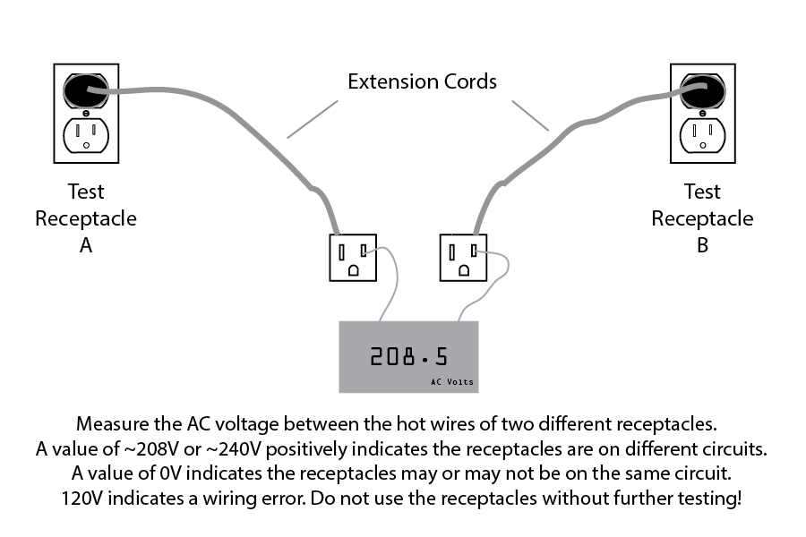
Plug an extension cord into a receptacle under test, then bring the female end of the cord near another receptacle. Using a voltmeter set to AC Volts, measure the voltage between the hot terminal (the shorter terminal) of the female end of the extension cord to the hot wire (again the shorter terminal) of the other receptacle.
- If you read approximately 208 or 240 volts, you have discovered two receptacles that must be on different circuits, which is a good thing, and the result we are looking for.
- If you measure 0 volts, that indicates that these receptacles are fed by the same phase, which may or may not be a different circuit.
- If you measure 120V, this means that one of the receptacles is reverse polarity. Do a full receptacle test procedure to figure out which receptacle is miswired, and do not use the miswired receptacle.
Method 3: Electronic Circuit Breaker Finder
Another method is to use an electronic “circuit breaker finder” or tracer:
http://www.kleintools.com/catalog/electrical-testers/digital-circuit-breaker-finder
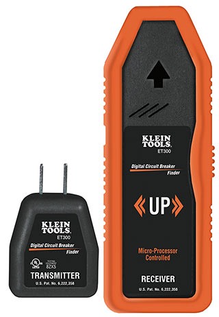
These tools require access to the breaker panel, and can with some ambiguity identify which breaker feeds the receptacle you are testing. The sending unit is plugged into the receptacle under test, and the receiver is passed over the circuit breakers in the panel. The unit beeps when it is over the circuit breaker supplying the receptacle under test.
Conclusion
Finding multiple circuits can be an adventure, and success often comes by pulling from a bag of tricks, rather than a specific procedure. Still, there’s usually a way to find at least two circuits in most rooms, even if you have to run a cord down the hall.
Don’t underestimate the value of an efficient system. Working to reduce your power consumption so that you’re not constantly trying to shoehorn a power hungry system into small rooms will save you a lot of hassle, and could potentially be a competitive advantage. It doesn’t take much to make a big difference – speakers 3dB more efficient will require half the amplifier power for the same output. Turning down your system 3dB will have a similar effect – if you normally require 4 circuits for audio, you could run on 2 circuits if you can accept 3dB less output.