By TJ Cornish, August 2013
We’ve had a few posts recently about blown up gear due to power problems. Here is a basic metering procedure that should give you a good indication of the safety of a standard North American receptacle (NEMA 5-15R or 5-20R).
Standard disclaimers:
- Performing this test can give you reasonable assurance that a receptacle is properly wired and functioning, however it does not guarantee that the receptacle is good – there are still possible fault conditions that may not be revealed with this test.
- Performing this test requires sticking conductive things – multi-meter probes – into an unknown electrical supply. This has the potential to create an electric shock hazard if you touch the metal tips of your meter probes (duh), and if things are really wrong, you may cause your multi-meter (especially if it’s a cheap one) to explode.
Proceed at your own risk (though testing is a lot less risky than plugging gear into an unknown receptacle).
Anatomy of a Receptacle
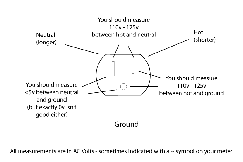
An electrical circuit is a loop. Power comes out of something, goes through the device you’ve plugged in, and then has to return to the source. If this loop is broken, no current will flow. In the NEMA 5-15 series receptacle, power comes out of the hot wire, flows through your device, and returns to the neutral conductor. The hot terminal is shorter than the neutral terminal. This keying is intentional to make sure that the device can’t be plugged in backwards.
The third terminal is the Ground terminal. This is a safety path back to the service panel that may conduct away fault currents in the event of a device fault.
What’s Supposed to Happen
When things are wired correctly and working normally, approximately 120 volts and up to either 15 or 20 amps of current, depending on the circuit’s capacity, are available for doing work. This energy flows out of the hot wire, through the connected device (the load), and returns to the neutral wire. As such, the hot and neutral wires are considered current carrying conductors.
The ground wire is not intentionally a current carrying conductor – if more than a small amount of current is flowing on the ground wire, that indicates a fault.
Testing Procedure
1. Set your multi-meter to AC Volts. Be sure that your multi-meter is capable of measuring line voltages. It is strongly recommended to get a meter that is rated Category III at 600 volts or better.
2. Insert one probe in the hot terminal, and the other in the neutral terminal. It doesn’t matter which one goes in which terminal for the AC measurements we will be doing. You should read between 110 and 125 volts AC. If you read higher than this range, DO NOT USE THIS RECEPTACLE. If you read lower than 110 volts, that indicates the circuit feeding this receptacle is heavily loaded, or there is a lot of wire between the service panel and where you are metering. It may be possible to use this receptacle, but you may encounter brown-out conditions which can also be hard on gear.
3. Measure between the hot terminal and the ground terminal. You should read between 110 and 125 volts AC. This reading should be roughly the same as your previous reading between hot and neutral. If you read outside this range, DO NOT USE THIS RECEPTACLE.
4. Measure between the neutral and ground terminal. You should read between 0 and 5 volts AC. If you read a bit more than 5 volts, the circuit may still be safe to use, but that indicates either the circuit supplying this receptacle is heavily loaded, or a long way from the service panel. If you read substantially more than 5 volts, DO NOT USE THIS RECEPTACLE.
5. Plug a high-current device such as a 500 watt PAR can or heater into the receptacle, and repeat all 3 measurements. What you should see is the voltage between hot and neutral should drop slightly – a volt or two, the voltage between hot and ground should drop similarly, and the voltage between neutral and ground should increase. If any of these values deviate more than a volt or two from your no-load testing, the receptacle is pretty soft. If the voltage between neutral and ground doesn’t increase when tested under load, that likely indicates a “cheater” receptacle, where the neutral and ground terminals are connected together inside the receptacle box, and the receptacle should not be used.
Common Faults
- Mis-wired receptacles are incredibly common – even in new, nice looking commercial construction. If you read values other than what is listed above, the receptacle is likely mis-wired: either a hot-neutral swap, or a hot-ground swap. Note that it is not possible to test for a neutral-ground swap using a multi-meter.
- Loose wiring. Since a multi-meter draws almost zero current when testing, it is possible for a receptacle to test normally, but under load, the loose connection opens up. Depending on which wire is loose and where the fault lies, the voltage may either go down below 120 volts, or it may even go up to 208 or 240 volts! This is why it is important to test your receptacles under load. Putting a heavy load on a circuit like a big light bulb or heater causes the receptacle and supply circuit to reveal their true colors.
- Wrong voltage supply. Virtually every building has multiple voltages in use – 120v, 208v, 240v, 277v, 480v, 600v, and others. It is possible to have a receptacle fed by a supply other than 120 volts – incredibly these dangerous situations can stay around for months or years.
Test, test, test! Get in the habit of unloading your multi-meter before you unload your truck. If the power is suspect, pack up and hit the road. “The show must go on” is a stupid motto. Expensive gear can be damaged, and people can be hurt. It’s just not worth it.